A grid-connected battery system for the storage of electrical energy from PV systems consists primarily of
The battery bank is composed of multiple battery strings, connected in parallel, which in turn consist of multiple individual batteries connected in series.
In principle, one can differentiate between battery systems with AC- and DC-coupled topologies.
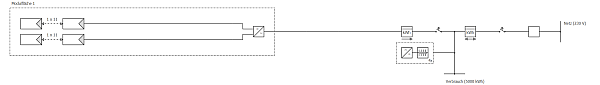
• In AC-coupled systems, the PV module, consumers, grid and battery components are coupled on the AC side. This means, there is at least one inverter (DC/AC) for the PV system and one (bidirectional, DC/AC and AC/DC) for the battery system. Those AC coupled systems are the most flexible in terms of compatibility, they are easy to retrofit into existing PV systems and they can load energy from the grid if necessary (e.g. for battery maintenance charging modes).
• In DC-coupled systems, the PV module and battery system are brought to the same voltage level and all connected on the DC side.
Here the battery system is directly connected with the DC cabling between the PV generator and the MPP tracker of the PV inverter. Thus, the battery system also needs a MPP tracker to be able to work with the variable voltage of the PV generator. One advantage is the easy retrofitting in existing PV systems.
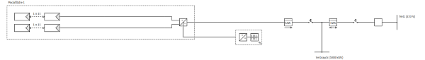
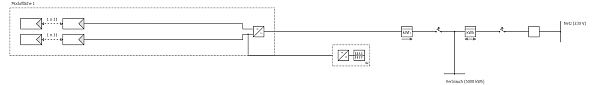
Here the battery system is connected in the DC intermediate circuit of the PV inverter, which means between MPP tracker (with downstream DC/DC step up converter) and the DC/AC converter. This has the advantage that the battery system does not need an own MPP tracker. These systems, however, cannot easily be retrofitted into existing PV systems.
In PV*SOL®, all of the above mentioned types of battery systems can be simulated.
In practice it should be noted that the connection to the consumer, the PV system and the battery system at the various phases of the electricity grid takes place in such a way that energy can be exchanged.
In PV*SOL® it is assumed that all consumers, PV inverters and battery inverters are properly connected. Consumers that are not connected to the battery system should therefore not be simulated. On the consumer side, only the consumption that is intended to be and can be covered by the PV system and/or the battery system is entered.
Battery systems can store energy from the PV system, deliver energy to consumers and, with specific types of battery charging, also accept energy from the grid. The charging controller, which operates on the basis of the logic outlined below, controls the energy flow.
If more energy is required by the consumers than can be provided by the PV system, the batteries are discharged. Here the provisions stated under 1.2 apply.
The charging of the batteries can be subdivided into current-regulated charging (I-charging), which is the standard case, and voltage-regulated charging, which essentially serves the maintenance of the batteries and can increase their lifespan. Here a distinction is made between a temporally limited charging procedure (U0-charging) and temporally unlimited trickle charging (U-charging).
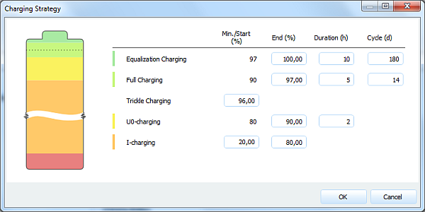
In PV*SOL®, an IU0U charging strategy is implemented, which is standard for the majority of lead acid or lead-gel batteries. Here an I-charge is followed by a brief UO-charge from a specified charge state, in order to prevent various aging effects. In addition, two further UO-charges are performed at an established rhythm, which can increase the lifespan of the batteries.
Complete charge, for around 5 hours, every 2 to 4 weeks
Equalization charge, for around 10 hours, every 4 to 6 months
If the batteries are at a high charge state and cannot be discharged, their self-discharge can be compensated for by means of a U-charge. This charging procedure is also called trickle charging.
I-charging means current-based charging. Also called bulk-load mode. This is the normal case, where the batteries are loaded with all the current available from the system. The battery voltage is then a function of the state of charge and load current. The discharge characteristics are similar to charging. So, the voltage rises with the state of charge, which makes it inefficient to load the batteries with full current when the batteries reach, say, 85 or 90 % of their full capacity.
The energy for I-charge is only taken from the PV system, never from the grid.
Then, normally, the U0 charge mode is used, which means the charge process is voltage based and has a predefined duration (that what the 0 stands for). This is also called boost mode. In general you try to load your batteries a little higher from 85% to 95% in 2 hours or so. This is important, especially for lead-acid based batteries, to ‘clean’ the anodes and cathodes from time to time and hence extend their lifetime.
This charging mode has high priority which means it is done with energy from the grid if no PV energy is available.
The trickle mode is kind of an idle mode. When the battery reaches the trickle SOC and no energy is demanded then only the losses due to self-discharge are compensated. The trickle mode is a U-charge mode, which means it is voltage-based, but not limited in time. It just ends when the battery has to discharge again.
In this mode, the (very low quantity of) energy can be covered by the PV system and the mains network.
Full and equalisation charge modes are U0-charge modes which mean they are also voltage based and limited in time, just like the boost mode.
These are just ‘maintenance programs’ to really fully load the batteries, clean them and equalize any voltage differences between them (since they tend to drift apart when connected in a large battery system).
These charging modes also have high priority which means they are done with energy from the grid if no PV energy is available.
Lithium-based batteries do not require a full charge and an equalization charge.
For batteries based on lead
For batteries based on lithium
