
Cable plan workspace > (Cable node toolbar) Editor
Various different cable nodes can be included in the cable plan using drag & drop.
Types of cable nodes
 |
 |
Bundles do not have an electrical function, only a mechanical one. They bundle cables. Therefore bundles do not have inputs or outputs. If you insert an interceptor node into a cable bundle, a bundle will then be inserted. |
  |
 |
T-plugs make it possible to electrically join 2 cables to a cable. There are positive and negative T-plugs. -> see also: Dimensioning |
 |
 |
Generator junction boxes connect several strings together. |
 |
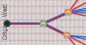 |
Coupling boxes connect several generator terminal boxes together. |
 |
 |
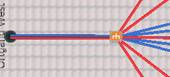
The cable grommets do not have an electrical function, only a mechanical one. They represent the path to the inverter and determine its distance. The distance to the inverter has an influence on the calculation of the cross section as well as the length of the incoming cable and therefore also on the loss calculation. |
 |
Interceptor nodes can be used to go around restricted objects, such as dormers for example. In automatic cabling, these interceptor node are used to achieve a right-angled path for individual cables. |
|
|
|
  |
The positive and negative poles of a module string can be swapped over. |
|
Module connection boxes are automatically generated and cannot be edited. |
Cable plan workspace > Side menu
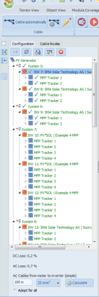
Side menu top: tree view of all electric nodes of all mounting surfaces with button bar
Context menu - Electric nodes
|
|
Cabling with |
Links the selected nodes with a cable node |
|
|
Sets cable cross section |
Sets the cross section of the string |
|
|
Change polarity |
Swaps positive and negative poles |
|
|
Remove |
Deletes the selected cable node(s) |
|
|
Remove all cable nodes |
Deletes all cable nodes |
Side menu bottom: tree view of all cable nodes of all mounting surfaces with button bar
|
|
Cable nodes can be selected and edited over the tree view. Multiple cable nodes can also be selected for editing by Multiselect (hold down CTRL key). Various different actions can be carried out irrespective of the selection: |
Context menu - Cable nodes
|
|
Cabling with |
Links the selected cable nodes with a cable node |
|
|
Sets the cable cross section |
Sets the cross section of the incoming and outgoing cable |
|
|
Rename |
Renames the cable node |
|
|
Connect automatically |
Determines the target node of an automatic cabling |
|
|
Edit |
Opens the cable node dialog box |
|
|
Remove |
Deletes the cable node(s) |
|
|
Remove all cable nodes |
Deletes all cable nodes |
Cable plan workspace > Editor > [Cable node name dialog box]
-> How to proceed:
Open the cable node dialog box by:
Double click on the cable node.
Click on the button " Set cable cross section" in the bottom side menu "Cable plan".
Click on "'Set cable cross section" in the context menu.
Click on "Edit" in the context menu.
Set the cross section of all incoming and outgoing cables.
As the cable cross section of an electronic node determines the assigned module cable and string cable, it overwrites the previously defined cross section of individual cables.
The cross section of an outgoing cable can be recalculated.
(Only applicable for mechanical functions such as bundling and cable grommets.)
For  cable grommets enter the distance after the cable grommet up to the inverter.
This distance has an influence on the calculation of the cross section, length of cable and losses.
-> See also: Cable list
You can set the position of the cable node on the mounting surface.
-> Object, position and orientation


