
-> Prerequisites:
Definition of the terrain with all shading objects and
Definition of module coverage
-> Configure a system as follows:
Start module configuration by:
 Configure module rows individually option in the Options dialog.
 Configure or select the context menu option
 The dialog Inverter is opened. Select a configuration.
-> see also: Inverter
Confirm your selection with OK.
->In the sidebar you can see the structure of the PV-system.
View Configuration:
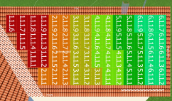
The modules are then divided into strings on the basis of this configuration. The assignment of a module to a string is indicated by the same color and in the module's label:
The PV modules are labeled in the number format I.M.S.P, which indicates the numbers of:
I = inverter, M = MPP tracker, S = string, P = PV module
 Show or hide the string colors and terms from the configuration
 The shade frequency also plays a major role in the module configuration: it decisively affects the optimum configuration of the modules in strings, as shading has a major influence on the array characteristic curve!
Adapt string course to shading:  Shade frequency
You can show and hide the side menu by clicking on the button  .
.
By clicking on an element (system, inverter, MPP tracker, string), the selected part of the system configuration is highlighted.
Configuration Rules:
! Modules may only be assigned to a configuration once!
! Configurations must be selected as they are. They cannot be expanded subsequently, only removed or created!
! Each module area becomes a subsystem unless you have created a system inverter by selecting 'Interconnect selected module areas' in the object tree of the dialog Inverter.
Further information can be found in the dialog Configured Module Areas.
Power optimizers can be assigned to the PV System, one or several Subsystems or one or several inverters in the side menu.
The selected system part is marked by a star .
.
The power optimizer option allows each PV module to be operated at maximum power independently of the other PV modules in the string. Since no mismatching losses occur in systems with power optimizers, they are automatically set to zero.
When taking over the 3d project to the main PV*SOL program, several subsystems are created automatically, if not all inverters of a subsystem are using power optimizers. The subsystems are shown in the system schematic and in the project report.
System inverter
A system inverter is an inverter with multiple module areas.
-> See also:
